Make Smart Home Automation Using Arduino Hackaday.io

(PDF) Smart Home Automation System using Arduino and Android Application
Smart Home Automation System using Arduino and IOT V. Sudharani1, D. Siva2, M. Vijaya Raju3. Block Diagram of experiment. 4. Specification of Components . 4.1 Arduino UNO Board . The . Arduino Uno. is a microcontroller board based on the ATmega328 (datasheet). It has 14 digital input/output pins
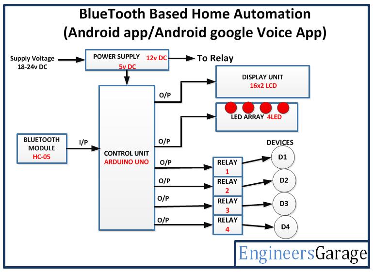
Bluetooth Based Home Automation Using Arduino Block Diagram
Testing: Home Automation with Arduino IoT Cloud & ESP32. After uploading the code, open the Serial Monitor. It will show WiFi connection is established and then the device is connected to Arduino IoT Cloud Dashboard. Open the dashboard now, so you can see the switch can be turned ON and OFF or enabled or disabled.
Home Automation using Arduino and Bluetooth module by Ayush Agarwal Medium
Working Principle IR Remote control home automation. In this project, we have used a simple Method for control (ON/OFF) a single home appliance device by a single button of Remote, this Method is known as Toggle [EVEN ODD] Method.As an example, we can turn ON and OFF of a device using the Remote button "1". At first, we will identify 4 buttons of the remote for controlling 4 devices.

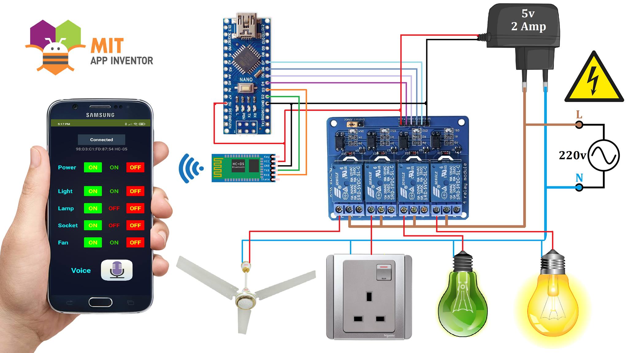
Voice controlled Home Automation project using Arduino
At first, we need to install the app on our smartphone, which is easily available in the play store. This app receives our Voice command and sends it to the Bluetooth module wirelessly. The Arduino decodes this command from the Bluetooth module. Then Arduino sends a command to the Relays to control the home appliances.
How to make Arduino based Home Appliance Control Hackster.io
The GSM Based Home Automation system is used to control home appliances by sending SMS from your Phone. This project is consists of Arduino, GSM SIM900 Module, 16×2 LCD module, and Relay Module. Where Arduino is the main microcontroller which controls the entire system. GSM Module is used to wireless communication with the phone, for.
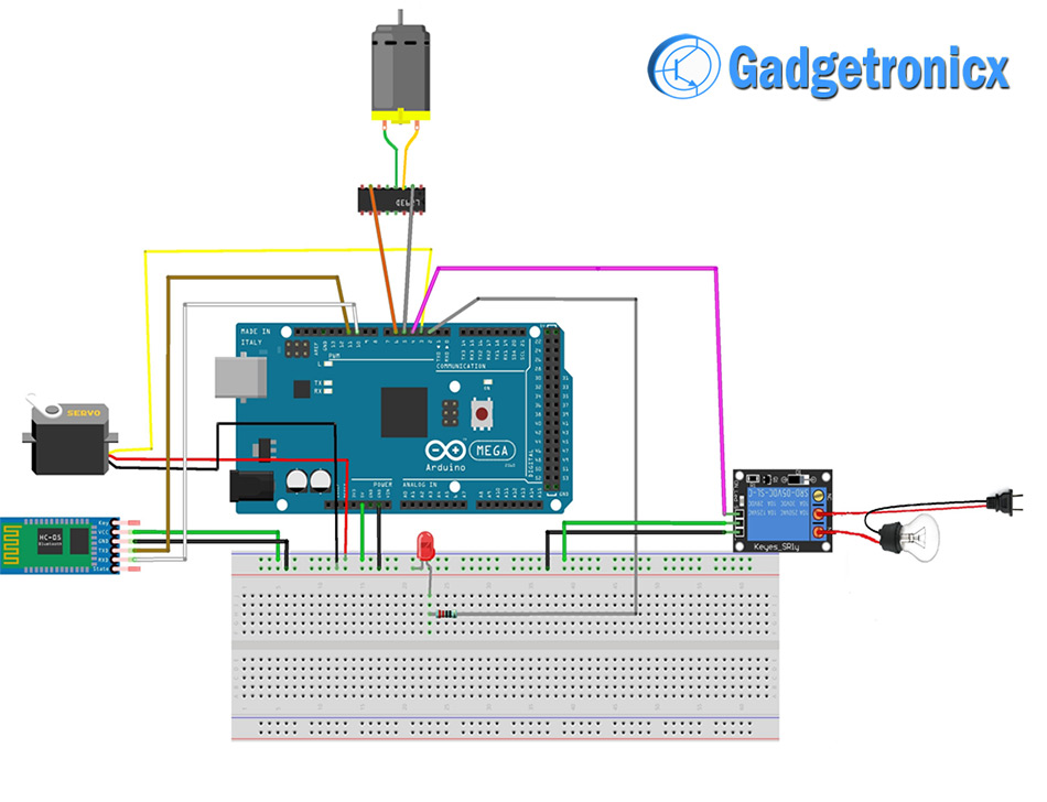
Voice controlled home automation using Arduino Gadgetronicx
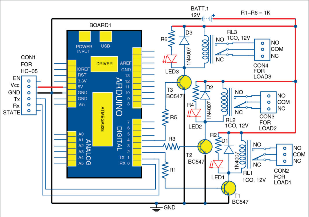
It is built around Arduino Uno R3 (Board1), HC-05 Bluetooth module, three relays (RL1 through RL3) and a few other components. This project demonstrates how to turn on/off the appliances connected with the relays using an Android app on a smartphone or tablet. Fig. 1: Block diagram of home automation system using Arduino Fig. 2: Circuit diagram.

Block diagram of Smart Home Automation System Download Scientific Diagram
Codes And Circuit Diagrams Code And Circuit Diagram For Home Automation System Using Arduino January 30, 2018 admin 95 Comments ** if you want to buy the entire package with a re-programmable Arduino Click Here ** 1) Home Automation System CODE :- String inputs; #define relay1 2 //Connect relay1 to pin 9 #define relay2 3 //Connect relay2 to pin 8
Home Automation Using Arduino Through Android Device DIY Project
Context 1. proposed system shown in Fig. 1 uses the wireless technology to control the home appliances with the help of Android Smart phone. The Android smart phone supports WiFi.
Bluetooth Controlled Home Automation System EngineersGarage
This Python script communicates with the Arduino BT board and sets up an ad-hoc communication protocol between the two devices, which allows controlling the behaviour of the Arduino BT board..
Make Smart Home Automation Using Arduino Hackaday.io
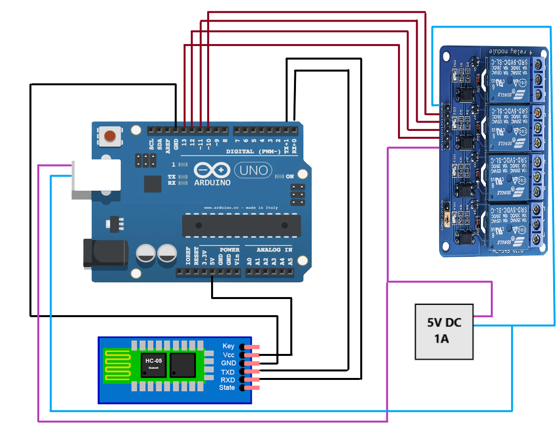
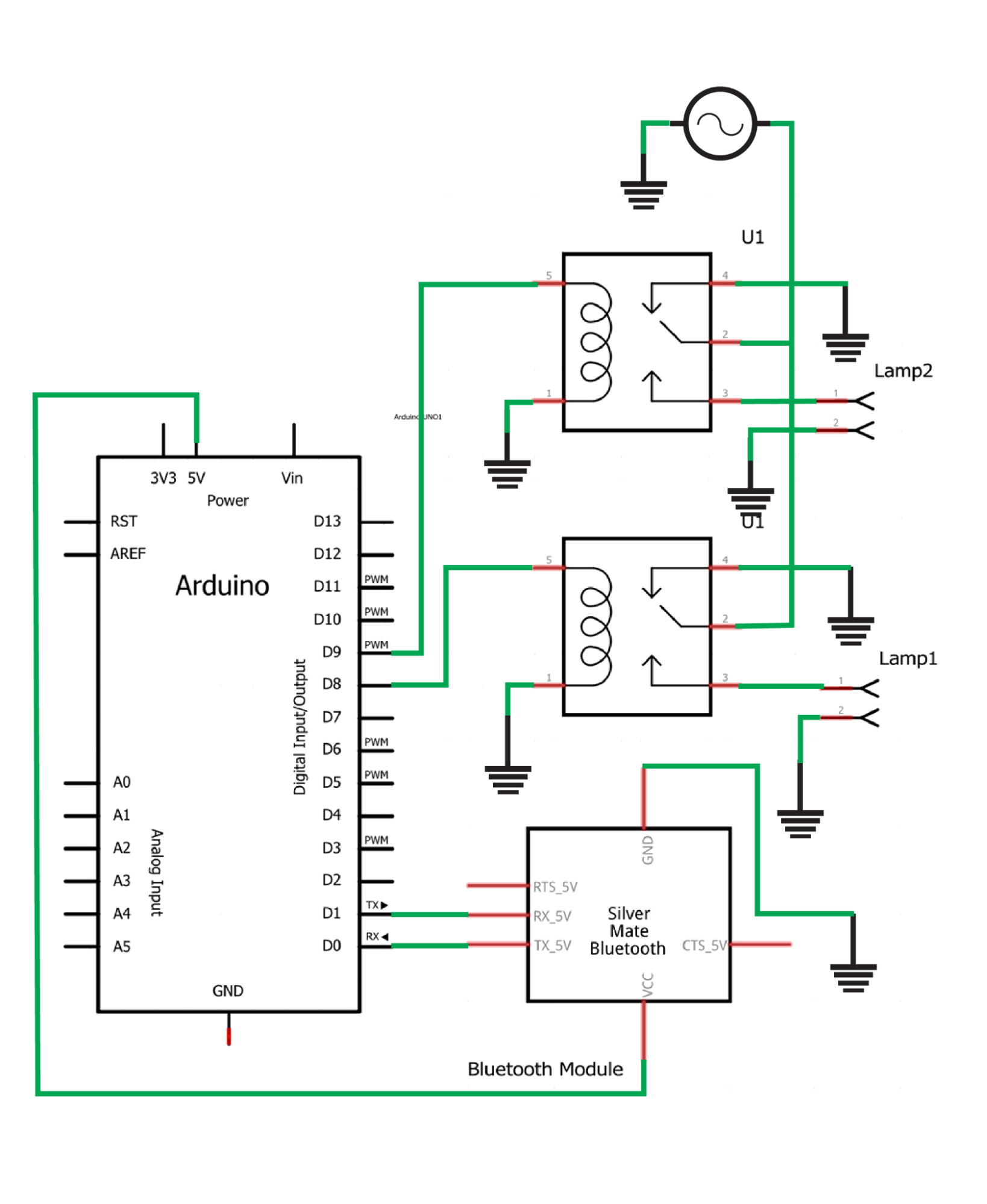
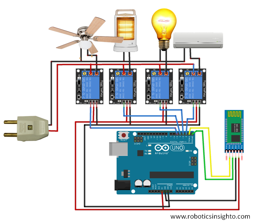
Block Diagram Connection Diagram of Bluetooth Controlled Home Automation Project In this section, we will explain the connections of the various components specified above with Arduino Uno to form the home automation system. Let us discuss them one by one. Arduino with HC-05 Bluetooth Module

Home Automation Using Arduino and Bluetooth Control Hackster.io
Block Diagram Connection Diagram of Voice Controlled Home Automation Project In this section, we will explain the connections of the various components specified above with Arduino Uno to form the home automation system. Let us discuss them one by one. Arduino with HC-05 Bluetooth Module

Home Automation System Using Gsm And Arduino Block Diagram Smart All in one Photos
The basic block diagram of the smart home system is shown in figure 1. A micro-controller is used to obtain values of physical conditions through sensors connected to it [4]. These integrated sensors such as the temperature IJSER © 2015 http://www.ijser.org
Home Automation Using Arduino Uno
Fig. 9: Block Diagram of Arduino based IR Remote controlled Home Automation System. Circuit Description. It is assumed that the reader has gone through the project how to get started with the arduino and done all the things discussed in it. Circuit of this system is very simple in this TSOP 1738 connected to digital pin 9 of Arduino, which detects 38 KHz IR frequency and relays are connected.

Home Automation Using Arduino And Esp8266 Module
1) Connect the Arduino's +5V and GND pins to the bus strips on the breadboard, as shown in the above circuit diagram. 2) Power the HC-05 module by connecting the 5V and GND pins to the bus strips on the breadboard. The HC-05 is powered using 5VDC but includes an on-board voltage regulator that generates a 3.3V supply to power the transceiver.
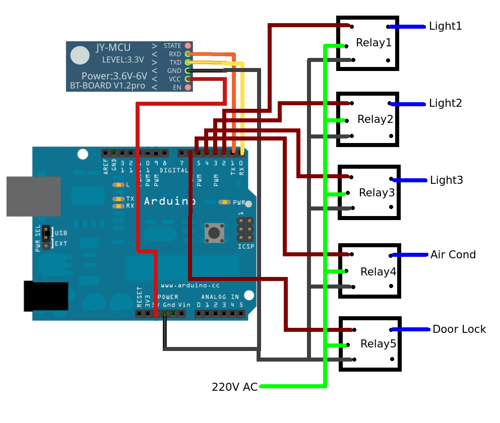
DIY home automation using Arduino, Relay and Bluetooth Module(HC05)
We designed this system for mobile phones having android platform to automate a Bluetooth interfaced Arduino which controls a number of home appliances like lights, fans, bulbs, door, water.
GSM Based Home Automation System using Arduino Project
In this project, a home automation system is designed which can be controlled by any smartphone. The automation system connects with the smartphone through Bluetooth. The smart phone sends control signals to switch home appliances ON or OFF by an android app through Bluetooth interface.
